In the current validation example, we investigate wind pressure value for both general structural design (Cp,10) and local structural design such as cladding or façade systems (Cp,1) based on EN 1991-1-4 flat roof example [1] and Japanese Wind Tunnel Data Base . The recommended setting for three-dimensional flat roof with sharp eaves will be described in the next part.

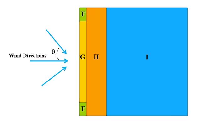
In the current validation example, we investigate wind pressure value for both general structural designs (Cp,10) and cladding or façade design (Cp,1) of rectangular plan buildings with EN 1991-1-4 [1]. There are three dimensional cases that we will explain more about if in the next part.
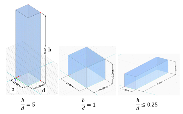
In the current validation example, we investigate wind force coefficient (Cf) of cube shapes with EN 1991-1-4 [1]. There are three dimensional cases that we will explain more about if in the next part.
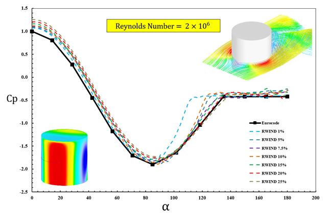
The available standards, such as EN 1991-1-4 [1], ASCE/SEI 7-16, and NBC 2015 presented wind load parameters such as wind pressure coefficient (Cp) for basic shapes. The important point is how to calculate wind load parameters faster and more accurately rather than working on time-consuming as well as sometimes complicated formulas in standards.
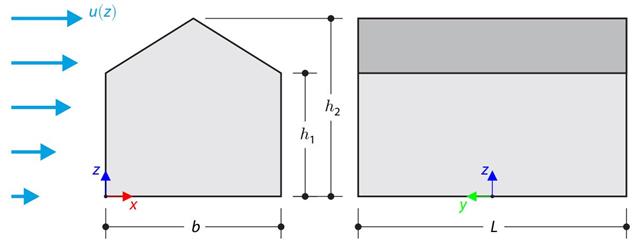
The verification example compares wind load calculation on a building with a duopitch roof using the standard EN 1991-1-4 and using CFD simulation in RWIND Simulation. The building is defined according to the sketch, and the inflow velocity profile is taken according to the standard EN 1991-1-4.
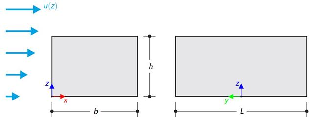
The verification example compares wind load calculation on a building with a flat roof using the standard EN 1991-1-4 and using CFD simulation in RWIND Simulation. The building is defined according to the sketch, and the inflow velocity profile is taken according to the standard EN 1991-1-4.